
| PAGE 2 OF 3 | [1] [2] [3] | DOWNLOAD PDF |
R. L Gregory
From Concepts and Mechanisms of Perception (1974, London: Duckworth) pp. 501-518 and Nature, 203, 4942, 274-295.
continued
It is well known that images in astronomical telescopes are shifted and degenerated by atmospheric disturbance. This becomes extremely important with large apertures and high magnifications: the disturbances prevent the detailed photographs which would be expected from the theoretical resolving power of large instruments. The disturbances take several forms: (1) The image may be shifted as a whole, in any direction, with varying frequency and amplitude. (2) Parts of the image may move in different directions simultaneously. (3) The image may be degenerated, especially with large aperture instruments, when the effective wave-length of the disturbance is less than the diameter of the objective. This produces a 'milkiness' of the image. This is quite different from the effect of shift when seen visually, though it may appear similar in a long-exposure photograph when the shifts produce blurring of contours and loss of fine detail.
It seems that visual observation can be preferable to photographic recording in lunar and planetary work, because the effects of the shifts of images can to some extent be avoided by visually sampling those moments when the agitation of the images is least marked. The purpose of the technique described here is to enable photographic telescopes to select moments of quiescence to build up a correctly exposed photograph.
It is clear from the kinds of disturbances encountered that any attempt to compensate the disturbances by introducing equal and opposite movements of the image on the plate will be unsatisfactory, when movements can occur in several directions in different parts of the image. Further, to get a servo-system to perform this task it would be necessary to feed it with information of the direction and velocity of the shifts, which is extremely difficult, while the servo itself would be subject to some over-shoot and tremor.
The technique under investigation is to take, first of all, a long-exposure photograph of the (atmospherically disturbed) image. The resulting photograph is statistically correct, in the sense that the major features will fall near the centre of intensity gradients produced by the random disturbance of the image. But, although the position of the contours will be nearly correct, fine detail is lost, hence the problem. This long-exposure photograph is processed, and the resulting negative is placed in its original position in the optical system, so that the fluctuating image now lies on the transparent negative. The image is now almost entirely cancelled by its negative. It is, however, most completely cancelled when the image most nearly corresponds to the negative. As the image is displaced, by the atmospheric or other disturbances, there is an increase in intensity. This is detected by a single photoelectric cell which covers the entire image plane, and so receives plenty of light. We can thus detect the presence of any shift of the image - though not the direction of shift - from increase in the output of the cell. The output rises with any discrepancy of the image from the statistically correct 'master' negative - not only shifts but also loss of focus and the 'milkiness' produced by regions of different refractive index smaller than the aperture of the instrument. (This last point I have established by means of a ripple tank.)
Having attained a signal indicating disturbance from the statistically correct image, it is a simple matter to use the signal to produce a second photograph free of disturbance. This may be done by using a second camera which shares the image with the first, by means of a beam splitter. This second camera is fitted with an electrically operated shutter which opens only when the output from the photocell is near its minimum value, corresponding to a close fit of the fluctuating image with the master negative.
In this way we separate informational integration from the integration of energy needed to expose the final picture, which is built up from many short exposures occurring whenever the image is close to the 'master'.
The preliminary experiments are limited to simulation of atmospheric disturbance, by placing an oscillating 'Perspex' sheet between the object and the optical system, and a ripple tank.
The beam splitter is a half-silvered mirror placed at 45?, so that the second camera (an 'Exacta' 35-mm. single-lens reflex) is provided with the same image as the large camera carrying the master negative and the photo-cell. The second camera is fitted with a specially made shutter, consisting of a pair of electromagnetic vibrator units (Advance type VI) which drive a pair of metal vanes shaped to form a square opening, increasing in size as the vanes are withdrawn by the opposed vibrator units. The circuit consists of an oscillator (400 c/s) allowing a.c. amplification from a bridge which is unbalanced by the photo-cell changing in resistance with increasing light, when the image loses register with the master. The amplified output is rectified, and used to energize the vibrator units to close the shutter.
An example of how a shifting image is improved is shown in Figs. 4a and b. Fig. 4 a was obtained from a long exposure of the Moon model while the 'Perspex' plate was oscillating about a vertical axis, to produce horizontal disturbance. The degeneration along the horizontal axis is very apparent. Fig. 4b shows the improvement obtained - the optical conditions being identical - when the shutter system is switched on. Some degeneration on the horizontal axis can still be seen: this may be further reduced by increasing the gain of the amplifier.
The improvement shown is given by a shutter open/closed ratio of about 6:1. This may be increased by increasing the gain in the present arrangement, or by introducing a gate, working the shutter as an all-or-none device. It is important to note that the improvement is from a blurred master negative identical with Fig. 4a since it was taken through the disturbance.
We are now simulating atmospheric disturbance with a layer of water agitated by an electromagnetic vibrator, driven from a low-frequency noise source. The resulting disturbances appear very similar to those experienced with an astronomical telescope. It remains to discover the efficiency of the technique under these more realistic conditions. It might then be directed to the Moon and the planets.
| (a) | (b) |
FIG. 4 First improved picture. (a) not sampled; (b) sampled. The disturbance is given by an oscillating perspex plate, using the first apparatus, as shown in Fig. 2. [NOTE: The limitations of reproduction for images in this publication renders the improvement seen in the actual images more difficult to see.]
It was clear that to get further, we would have to embark on a major instrument design and building project: we would have to stretch our abilities and resources to the limit. It would take an unpredictable amount of time, money and effort to build an adequate instrument to make use of the idea effectively on a telescope. Also, we were hardly in the right kind of department - was this anything to do with psychology? (Actually, I now think that relating real-time data to a stored average may be extremely relevant to psychology; but I did not realise this at the time.) Would building a telescope camera be acceptable in the context of experimental psychology? Here we were particularly fortunate to be in the University of Cambridge, for Cambridge has a long and well-justified tradition of tolerating individual foibles. The head of the department, Professor Oliver Zangwill, was tolerant, and the department of astronomy gave every encouragement and help - allowing us the sole use of a telescope for a year. This was the much loved century-old Thorrowgood refractor, in the care of Dr David Dewhurst, who was especially concerned with our project. The telescope is small, only eight inches in aperture; but it is sturdily built and well able to take the weight of our apparatus. We added a ring of red safe lights in the dome and replaced the nineteenth-century weight-driven drive clock with a synchronous motor driven from an accurate oscillator and - the fact is - we had an awful lot of fun and excitement in that little dome with its old brass telescope. Lastly money - we were given a generous grant from the Paul Fund of the Royal Society. This Fund exists to support the development of novel apparatus likely to be of scientific importance but of limited financial interest. It was a great day when all this came through, and we were able to plan our instrument for making more effective use of telescopes for probing the sky.
FIG. 5 Layout of second sampling camera. This is a side elevation of the sampling camera showing all main optical and mechanical features, except the final-picture camera which is mounted at (e).
(a) Mounting flange, for fixing camera to a telescope.
(b) Mixing cube, 5000 of light to the master plate (f), and 5000 to the final-picture camera (e), (not shown) via the sampling shutter, (d).
(c) Secondary lens, imaging telescope objective at:
(d) the sampling shutter, shown in Fig. 7, allowing, when open, light to reach:
(e) the final picture camera (not shown).
(f) is a manually operated photographic shutter for exposing:
(g) the master plate, whose holder is shown in Fig. 6.
(h) While sampling, light passes through the shutter (f) and the master plate (g) via mirrors h1 and h2 to:
(j) the photomultiplier which provides signals to the analogue computer, to actuate the sampling shutter (d), when the image most closely matches the master negative when the photomultiplier current is near a minimum: indicating that the fluctuating image is most nearly undisturbed - and so is the best representation of the object.
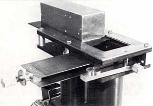
FIG. 6 Master Negative slide holder and locating system. The Master Negative plate is in the back square hole (top front) which is revealed when the mirror assembly (top), which sends light to the photomultiplier in further tube, (bottom) is slid back, as in this picture. The double dark slide is shown withdrawn, as when the plate is being exposed or when sampling is taking place. (The mirror assembly would however be slid forward over the Master Negative.)
The sampling camera was built by Stephen Salter, a dedicated engineer who applied all his skill. A darkroom was set up in the Thorrowgood dome by Philip Clark, who did trojan work organising temperature baths and fixing up a high speed processing service for the master plates. All through that incredibly wet summer of 1966 we strived to get improved pictures through gaps in the clouds.
The apparatus may be seen in the following figures. The general design of the sampling camera is shown in Fig. 5 and details such as the master plate location system (Fig. 6), the high speed on-demand sampling shutter, which presented the greatest difficulties. The problem here was to provide on-demand exposures down to about one milli-second, and this by mechanical means is quite surprisingly difficult. (Photographic shutters 'cheat' by employing pre-wound springs providing stored energy, so that they are not truly on-demand; or focal plane blinds whose moving slits give short exposures to each part of the film, though the entire exposure is quite long). We were helped by the fact that the image forming light in a telescope crosses near the final image, to make a small cross-sectional disk, which may be occluded with a small aperture shutter. The size of this disk depends on the optics of the telescope, but is generally only about one tenth of an inch in diameter. By placing our shutter exactly at this position of minimum required aperture it proved possible to get sample exposures down to just over one millisecond, with electromagnetic actuators suitably matched to thin steel blades. The arrangement, designed and built by Stephen Salter, is shown in Fig. 7.
There may be no gain with a faster shutter (except for work on the sun) for there must be sufficient time to collect enough quanta for a reliable correlation estimate. We would however like to try switched image-intensifiers, as non-mechanical shutters. It would also be nice to avoid photographic processing for the Master Negative, by some kind of electronic image storage.
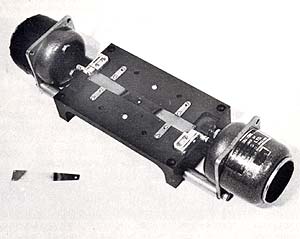
FIG. 7 Second sampling shutter, designed and made by Stephen Salter, using a pair of electromagnetic actuators (at ends) to deflect a pair of steel strips (feeler gauges) each having a small hole at its end: the holes coincide to allow light through when actuated by a sampling signal. (The feeler gauges are mounted with phosphor bronze pivot strips, in a mechanical matching transformer arrangement to give maximal efficiency.)
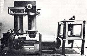
FIG. 8 Second sampling camera, on bench test. The randomly agitated water bath for simulating atmospheric disturbance is to the right with a pair of 90 prisms for passing the light from the object (off picture to the right) vertically through the water. The sampling camera is shown with its side plates removed, but otherwise complete, with the final - picture camera (partly hidden) at extreme left.
The camera can be seen on bench test in Fig. 8. A result, shown as a comparison pair of sampled and non-sampled pictures is shown in Fig. 9. The bench test improvement is really dramatic.
We obtained encouraging if not really conclusive results on the Cambridge telescope (Fig. 10) getting the kind of improvement apparent in Fig. 12 though this could have been due to chance improvements of the conditions between the sampled and unsampled pictures. We had enormous difficulty with the tracking of the telescope: we could only hope to get results when it was tracking the object (planet or moon) almost within the resolution of the telescope over a sampling period of about 30 minutes. This turned out to be extraordinarily difficult, with any telescope we have met, and has led to the building of a photo-electrically guided tracking corrector, which is now (Feb. 1972) being tested.
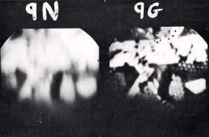
FIG. 9 Example of disturbed picture improvement by sampling. Both pictures are taken through the same disturbance (randomly agitated water) but 9G is sampled while 9N is a normal exposure. The unsampled, 9N picture is the same as the Master Negative used for obtaining 9G by sampling. So this gives a fair idea of the amount of improvement obtained on bench test. (Unfortunately there are technical problems which have, so far, prevented comparable improvement on telescopes. I believe these difficulties will be overcome.)
continues
![]()